-20240621-121518.png?inst-v=5bf62ed3-a19e-46f0-82f2-f0643494e2e9)
Device identification
设备:Shelly Wave Pro 2PM (US)
US Part number/Ordering Code: QUSW-0A2P25US
Z-Wave 产品类型 ID: 0x0002
Z-Wave 产品 ID:0x008D
Z-Wave 制造商:Shelly Europe
Z-Wave 制造商ID: 0x0460
此设备同时支持 Z-Wave®(网状)和 Z-Wave® 长距离(星型)网络拓扑。在设备加入过程中,您必须选择一种网络拓扑。
以下带有 * 标记的部分仅适用于 Z-Wave® 网状网络入网,不适用于 Z-Wave® Long Range 星型网络入网。
Terminology
Shelly Wave Pro 系列
Shelly Wave Pro 系列是一系列适用于家庭、办公室、零售商店、制造设施和其他建筑的设备。Pro 设备可在配电箱内采用 DIN 轨安装,非常适合新建工程。所有 Shelly Wave Pro 设备都可通过 Z-Wave 实现控制与监测® network.
Short description
该设备是一款可安装在DIN导轨上的双通道带功率测量的智能开关。它可控制两个独立电器的开/关功能,单通道负载高达12.5 A(总计25 A)。兼容开关(默认)和按钮。
Basic functions
SmartStart
Assocciations
可作为 Z-Wave 中继器使用
Switching On/Off load connected to O (O1)
Switching On/Off load connected to O2
Automatically switching On/Off load connected to O (O1)
Automatically switching On/Off load connected to O2
测量所有已连接负载的功耗 (W) 和能耗 (kWh)。
测量连接到 O (O1) 的负载的功耗 (W) 和能耗 (kWh)。
测量连接到 O2 的负载的功耗 (W) 和能耗 (kWh)。
OTA - Over-The-Air firmware update
Operational Instructions
Main applications
Residential
MDU (Multi Dwelling Units - apartments, condominiums, hotels, etc.)
Light commercial (small office buildings, small retail/restaurant/gas station, etc.)
Industrial (factories, power plants, water processing, refineries, etc.)
Government/municipal
University college
Farming
Integrations
Shelly Wave 设备基于 全球领先的智能家居技术——Z-Wave.
这意味着 Shelly Wave 可与所有 certified 支持 Z-Wave 通信协议的网关。
为确保Shelly Wave产品的功能在您的网关上得到支持,我们会定期将我们的设备与不同的Z-Wave网关进行兼容性测试。
Simplified internal schematics
Device electrical interfaces
Inputs
2 switch/push-button inputs on screw terminal
3 power supply inputs on screw terminals: N, 2 L
Outputs
2 relay outputs with power measurement on screw terminal
Connectivity
Z-Wave: 不安全, S0 安全, S2 未认证安全, S2 已认证安全
Safety features
Protection
Overheat Protection
Device has internal Overheat protection. If the temperature exceeds predefined values 80°C for more than 5s, the Device will:
switch off its own output
send the Notification Report to the gateway (Overheat detected)
LED 灯将按上述方式响应(查看检测到过热时的 LED 闪烁模式)
NOTE: The Overheat protection is always active and cannot be disabled.
Additional description above under chapter Notification for Overheat detected.
Overcurrent Protection
Device has internal Overcurrent protection. If the current exceeds 12.5A +10 % for more than 5s on O1, or if the current exceeds 12.5A+10% for more than 5s on O2, or if the current exceeds 25A +10 % for more than 5s on O1 + O2, the Device will:
switch off its own output
sends the Notification Report to the gateway (Overcurrent detected)
LED 灯将按上述方式响应(查看检测到过流时的 LED 闪烁模式)
NOTE: The Over-current protection is always active and cannot be disabled.
Additional description above under chapter Notification for Over-current detected.
Overvoltage Protection
设备具有内置过电压保护。该保护适用于标准电源电压 230 V AC。若电压超过 240 V AC+15%(278 V AC)并持续超过 5s,设备将:
switch off its own output
sends the Notification Report to the Gateway (Overvoltage detected)
LED 灯将按上述方式响应(查看检测到过压时的 LED 闪烁模式)
NOTE: The Over-voltage protection is always active and cannot be disabled.
Additional description above under chapter Notification for Over-voltage detected.
Supported load types
Resistive (incandescent bulbs, heating devices)
Capacitive (capacitor banks, electronic equipment, motor start capacitors)
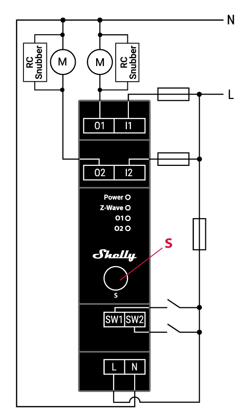
带 RC 吸收器的感性负载(LED 灯驱动器、变压器、风扇、冰箱、空调)
User interface
S button and operating modes
Settings mode:
Is required to start the desired procedure, for example: adding (inclusion (*not available for Long Range devices)), removing (exclusion), factory reset, etc. It has a limited operating time. After completing the procedure in Setting mode, the Device automatically switches to Normal mode.
-
Entering Setting mode:
按住设备上的 S 按钮,直到 LED 变为纯蓝色常亮。
An additional quick press on the S button changes the menu in an infinite loop.
菜单 LED 状态在 10s 后将超时,然后再次进入正常模式。
S button’s functions
手动将设备添加到 Z-Wave 网络(*不适用于长距离入网)
手动将设备从 Z-Wave 网络中移除
Factory Reset the Device
LED 信号指示
General rules
Switching between Normal and Settings mode is done by press and hold the S button.
LED 常亮 means that you are in the Settings mode (this is not valid for Plugs). Once in settings mode, switch to normal mode goes automatically after 10s.
如果 LED 不在报警模式,将在 30min 超时后熄灭。按下 S 按钮或对设备断电重启将唤醒 LED 30min。
在模块启动期间,LED 将以模式 5 闪烁(蓝色亮 0,2s/红色亮 0,2s),持续 4-5 s。
正常模式 LED 状态:正常模式指设备功能稳定,可无限期保持的状态。
LED 类型:RGB 可调光
Normal mode
Removed/Excluded
LED 将闪烁 blue in Mode 1 for 30min after every power cycle and 10min after S button pressed.

Added/Included
LED 将闪烁 green in Mode 1 for 30min after every power cycle and 10min after S button pressed.

Settings in progress
Factory reset and reboot
出厂重置期间,LED 将变为常亮的 green for approx. 1sec, then the blue and red LED 将以 0,1s 亮 / 0,1s 灭 闪烁约 2sec.
Adding / Removing
在添加或移除过程中,LED 将闪烁 blue in Mode 2.

OTA firmware updating
在 OTA 更新期间,LED 将闪烁 blue and red in Mode 2.

检查 AC 或 DC 电源电压
在检查电源时,LED 将闪烁 blue and red in Mode 5.

Settings mode with S button
Adding / Removing menu selected (*adding not available for Long Range inclusion)
选择菜单时 LED 将为 blue, for maximum of 10 seconds.
Adding / Removing menu - while pressing S- button - Add/Remove process selected (*adding not available for Long Range inclusion)
执行菜单时 LED 将闪烁 blue in Mode 3.

Factory reset menu selected
选择菜单时 LED 将为 red, for maximum of 10 seconds.
Factory reset - while pressing S - button - Factory reset process selected
执行菜单时 LED 将闪烁 red in Mode 3.

Alarm Mode
Overcurrent detected O
LED 将闪烁 red in Mode 4

模式 4 / 1 次 LED 亮 0,2s / 灭 0,2s + 灭 2s 的重复序列
Overheat detected
LED 将闪烁 red in Mode 4

模式 4 / 2 次(LED 亮 0,2s / 灭 0,2s)+ 灭 2s 的重复序列
Overcurrent detected O1
LED 将闪烁 red in Mode 4

模式 4 / 4 次(LED 亮 0,2s / 灭 0,2s)+ 灭 2s 的重复序列
Overcurrent detected O2
LED 将闪烁 red in Mode 4

模式 4 / 5 次(LED 亮 0,2s / 灭 0,2s)+ 灭 2s 的重复序列
Overvoltage detected
LED 将闪烁 red in Mode 4

模式 4 / 7 次(LED 亮 0,2s / 灭 0,2s)+ 灭 2s 的重复序列
电源 LED
LED 类型:红色
LED 将为 red solid if power supply is connected.
输出(O、O1、O2,…)LED
LED 类型:红色
LED 将为 red solid if the Output relay is closed.
LED 闪烁模式
Technical Specifications
Power supply |
110 - 240 V AC,50/60 Hz |
|
Power consumption |
< 0.3 W |
|
功率测量 [W] |
Yes |
|
最大开关电压 AC |
240 V |
|
最大开关电流 AC |
每通道 12.5 A,总计 25 A |
|
最大开关电压 DC |
不适用 |
|
最大开关电流 DC |
不适用 |
|
Overheating protection |
Yes |
|
Overcurrent protection |
Yes |
|
Overvoltage protection |
Yes |
|
Long range network |
Distance (depends on local condition) |
Up to 80 m indoors (262 ft.) or up to 1000 m outdoors (3281 ft.) |
Z-Wave® repeater |
No |
|
Z-Wave® frequency bands |
912.0 MHz |
|
Mesh network |
Distance (depends on local condition) |
Up to 40 m indoors (131 ft.) |
Z-Wave® repeater |
Yes |
|
Z-Wave® frequency bands |
908.4 MHz |
|
CPU |
Z-Wave® S800 |
|
尺寸(H x W x D) |
94x19x69 ± 0.5 mm / 3.70x0.75x2.71 ± 0.02 in |
|
Weight |
75 g / 2.65 oz. |
|
Mounting |
DIN rail |
|
Screw terminals max. torque |
0.4 Nm / 3.54 lbin |
|
Conductor cross section |
0.5 to 2.5 mm² / 20 to 14 AWG (green connector) |
|
Conductor stripped length |
6 to 7 mm / 0.24 to 0.28 in (green connector) |
|
Shell material |
Plastic |
|
Color |
Black |
|
Ambient temperature |
-20°C to 40°C / -5°F to 105°F |
|
Humidity |
30% to 70% RH |
|
Max. altitude |
2000 m / 6562 ft. |
|
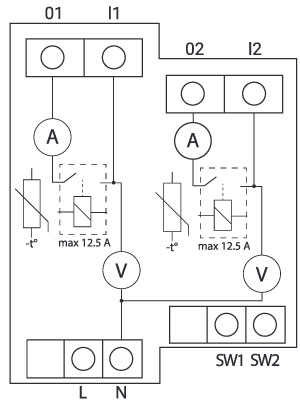
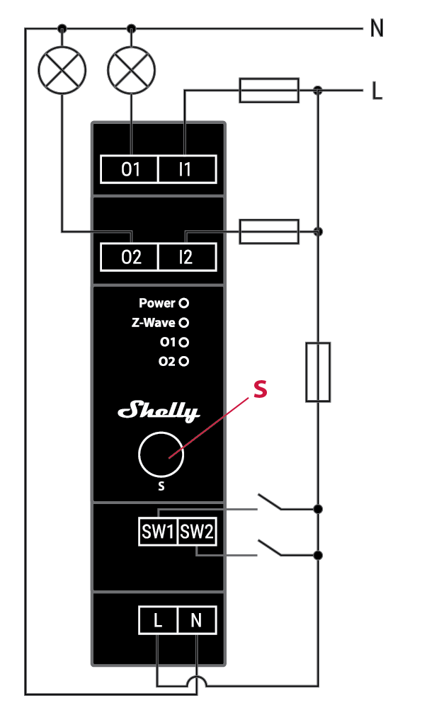
Basic wiring diagram
Fig. 1 |
Fig. 2 |
Legend
Device terminals:
N: Neutral terminal
L: 火线端子 (110-240 V AC)
SW (SW1): Switch/push-button input terminal (controlling O (O1))
SW2: Switch/push-button input terminal (controlling O2)
I1: Load circuit 1 input terminal
I2: Load circuit 2 input terminal
O (O1): Load circuit (1) output terminal
O2: Load circuit 2 output terminal
Wires:N: Neutral wire
L: Live 电线 (110-240 V AC)
Button:S: S button
Connect the load to the O1 and O2 terminal of the Device and the Neutral wire, as shown on Fig. 1. Connect the Live wire to an i terminal of the Device.
Connect the Live wire to the Device L terminal, and the Neutral wire to the N terminal. Connect the two switches or a push-buttons to the Device SW1 and SW2 terminal and the Live wire.
关于 Z-Wave®
关于 Z-Wave®

Z-Wave® 协议是一种可互操作的、无线的、基于射频(RF)的通信技术,专为住宅和轻型商用环境中的控制、监测和状态读取应用而设计。成熟、经验证且已广泛部署,Z-Wave® 目前在无线控制领域稳居全球市场领导者地位,为数以百万计的人们在日常生活的各个方面带来价格亲民、可靠、易于使用的“智能”产品。
互操作性一直是 Z-Wave 协议的核心,同时还包括向后兼容性、安全性和可靠性等特性。所有 Z-Wave 设备都可以在任意 Z-Wave 网络中与其他通过 Z-Wave 认证的设备一起运行,不受品牌或制造商限制。网络中所有由市电供电的节点都会充当中继器,无论供应商是谁,从而提升网络的可靠性。在 Z-Wave 生态系统中,有 4000+ 款通过 Z-Wave 认证、支持向后和向前兼容的产品;目前市场上的设备数量已超过 1 亿台。
凭借在市场上超过20年的历程,Z-Wave 技术具备行业领先的安全防护措施,让您的家庭网络更智能、更安全。
将设备添加到或从 Z-Wave® 网络中移除
将设备添加到 Z-Wave 网络(加入)
Note! 在进行 Security 2(S2)添加(加入)时,将出现一个对话框,要求您输入相应的 PIN 码(5 个带下划线的数字),该 PIN 码标注在设备侧面的 Z-Wave DSK 标签上,以及包装内附的 Z-Wave DSK 标签上。
IMPORTANT: The PIN Code must not be lost.
SmartStart adding (inclusion)
支持 SmartStart 的产品可通过在提供 SmartStart 加入功能的网关上扫描设备上的 Z-Wave QR 码,添加到 Z-Wave 网络。无需执行任何其他操作,SmartStart 设备在通电并位于网络附近后,将在 10 分钟内自动添加。
With the gateway application scan the QR code on the Device label and add the Security 2 (S2) Device Specific Key (DSK) to the provisioning list in the gateway.
Connect the Device to a power supply.
检查蓝色LED在模式1中是否闪烁。若是,则设备尚未加入Z-Wave®网络。
将设备连接到电源后,几秒钟内会自动启动添加过程,设备将自动加入Z-Wave网络。
在添加过程中,蓝色 LED 将以模式 2 闪烁。
如果设备已成功加入Z-Wave®网络,绿色LED将在模式1中闪烁。
Adding (inclusion) with the S button (*not available for Long Range inclusion)
Connect the Device to a power supply.
检查蓝色LED在模式1中是否闪烁。若是,则设备尚未加入Z-Wave®网络。
Enable add/remove mode on the gateway.
要进入设置模式,按住设备上的 S 按钮,直到 LED 变为纯蓝色常亮。
松开后再次按住(> 2s)设备上的 S 按钮,直到蓝色 LED 以模式 3 开始闪烁。松开 S 按钮将启动学习模式。
在添加过程中,蓝色 LED 将以模式 2 闪烁。
如果设备已成功加入Z-Wave®网络,绿色LED将在模式1中闪烁。
Note! In Setting mode, the Device has a timeout of 10s before entering again into Normal mode.
Adding (inclusion) with a switch/push-button (*not available for Long Range inclusion)
Connect the Device to a power supply.
检查蓝色LED在模式1中是否闪烁。若是,则设备尚未加入Z-Wave®网络。
Enable add/remove mode on the gateway.
Toggle the switch/push-button connected to any of the SW terminals (SW, SW1, SW2, etc.) 3 times within 3 seconds (this procedure puts the Device in Learn mode*). The Device must receive on/off signal 3 times, which means pressing the momentary switch 3 times, or toggling the switch on and off 3 times.
在添加过程中,蓝色 LED 将以模式 2 闪烁。
如果设备已成功加入Z-Wave®网络,绿色LED将在模式1中闪烁。
*Learn mode - a state that allows the Device to receive network information from the gateway.
将该设备从 Z-Wave® 网络中移除(排除)
Note! 该设备将从您的 Z-Wave 网络中移除,但任何自定义配置参数都不会被清除。
Removing (exclusion) with the S button
Connect the Device to a power supply.
检查绿色LED在模式1中是否闪烁。若是,则设备已加入Z-Wave®网络。
Enable add/remove mode on the gateway.
要进入设置模式,按住设备上的 S 按钮,直到 LED 变为纯蓝色常亮。
松开后再次按住(> 2s)设备上的 S 按钮,直到蓝色 LED 以模式 3 开始闪烁。松开 S 按钮将启动学习模式。
在移除过程中,蓝色 LED 将以模式 2 闪烁。
如果设备已成功从Z-Wave®网络中移除,蓝色LED将在模式1中闪烁。
Note! In Setting mode, the Device has a timeout of 10s before entering again into Normal mode.
Removing (exclusion) with a switch/push-button
Connect the Device to a power supply.
检查绿色LED在模式1中是否闪烁。若是,则设备已加入Z-Wave®网络。
Enable add/remove mode on the gateway.
Toggle the switch/push-button connected to any of the SW terminals (SW, SW1, SW2,…) 3 times within 3 seconds (this procedure puts the Device in Learn mode). The Device must receive on/off signal 3 times, which means pressing the momentary switch 3 times, or toggling the switch on and off 3 times.
在移除过程中,蓝色 LED 将以模式 2 闪烁。
如果设备已成功从Z-Wave®网络中移除,蓝色LED将在模式1中闪烁。
Factory reset
Factory reset general
恢复出厂设置后,所有自定义参数和已存储的数值(kWh、关联、路由等)都将恢复为默认状态。分配给设备的 HOME ID 和 NODE ID 将被删除。仅在网关丢失或无法运行时使用此重置步骤。
Factory reset with the S button
Note! Factory reset with the S button is possible anytime.
要进入设置模式,按住设备上的 S 按钮,直到 LED 变为纯蓝色常亮。
多次按下 S 按钮,直到 LED 变为纯红色常亮。
按住(> 2s)设备上的 S 按钮,直到红色 LED 以模式 3 开始闪烁。松开 S 按钮将启动出厂重置。
在出厂重置期间,LED 将变为绿色常亮约 1s,然后蓝色和红色 LED 将以模式 3 开始闪烁约 2s。
如果出厂重置成功,蓝色 LED 将以模式 1 闪烁。
Factory reset with a switch/push-button
Note! Factory reset with a switch/push-button is only possible within the first minute after the Device is connected to a power supply.
Connect the Device to a power supply.
Toggle the switch/push-button connected to any of the SW terminals (SW, SW1, SW2,…) 5 times within 3 seconds. The Device must receive on/off signal 5 times, which means pressing the push-button 5 times, or toggling the switch on and off 5 times.
在出厂重置期间,LED 将变为绿色常亮约 1s,然后蓝色和红色 LED 将以模式 3 开始闪烁约 2s。
如果出厂重置成功,蓝色 LED 将以模式 1 闪烁。
Remote factory reset with parameter with a gateway
Factory reset can be done remotely with the settings in Parameter No. 120.
Security and Device Specific Key (DSK)
该设备支持最新的 Security 2(S2)功能。S2 由强大的 AES 128 加密协议处理,这意味着 S2 使 Z-Wave® 成为目前最安全的物联网(IoT,Internet of Things)安全平台。要充分利用本产品及其 Security 2 功能,必须使用支持 Security 2 的 Z-Wave® 网关。
Authenticated Control
Out-Of-Band DSK for adding (inclusion)
May be used by most implementations
The Device also supports Security 2 Authenticated, Unauthenticated, and Unsecure adding (inclusion).
Note! 将设备添加到支持 Security 2(S2)的 Z-Wave 网络时,需要输入 Z-Wave 设备专用密钥(DSK)的 PIN 码。你可以在设备侧面的标签上找到它,包装内也附有一份副本,务必妥善保管,切勿丢失。请勿从设备上移除 Z-Wave DSK 标签。可将包装内的标签作为备份使用。
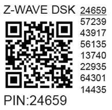
The first five digits of the key are highlighted or underlined to help the user identify the PIN Code part of the DSK text. The DSK is additionally represented with a QR Code as shown on the image.
Z-Wave® DSK 标签和二维码(示例)
A 请求加入 S2 Access Control Class 或 S2 Authenticated Class 的节点会在通过 RF 传输其密钥之前,将其公钥的第 1..2 字节设为零(0x00)以进行混淆。
The DSK may be used for out-of-band (OOB) authentication.
The including gateway may use a QR code scanning device to read the entire DSK of the joining device and match it with the obfuscated public key received via RF from the joining device.
Setting Parameters
Parameter No. 1 - SW (SW1) Switch type
This parameter defines how the Device should treat the switch (which type) connected to the SW (SW1) terminal.
Value size: 1 Byte
Default value: 2
Values & descriptions:
0 - momentary switch (push button),
1 - toggle switch (contact closed - ON / contact opened - OFF),
2 - toggle switch (Device changes status when switch changes status)
Parameter No. 2 - SW2 Switch type
This parameter defines how the Device should treat the switch (which type) connected to the SW2 terminal.
Value size: 1 Byte
Default value: 2
Values & descriptions:
0 - momentary switch (push button),
1 - toggle switch (contact closed - ON / contact opened - OFF),
2 - toggle switch (device changes status when switch changes status)
Parameter No. 6 - Inputs SW1 & SW2 Swap
This parameter allows to swap the operation of switches connected to inputs SW1 and SW2 without changing the wiring.
Value size: 1 Byte
Default value: 0
Values & descriptions:
0 - default (SW1 - O1, SW2 - O2),
1 - swapped (SW1 - O2, SW2 - O1)
Only used for Wave Shutter and other Devices with 2 Switch inputs (SW1 and SW2) like Wave 2PM,…
Parameter No. 16 - Outputs O1 & O2 swap (Only used for Wave Shutter and other Devices with 2 Outputs (O1 and O2) like Wave 2PM,…)
This parameter allows to swap the operation of outputs O1 and O2 without changing the wiring (in case of an invalid motor connection) to ensure proper operation.
Values size: 1 Byte
Default value: 0
Values & descriptions:
0 - default (O1 - OPEN, O2 - CLOSE),
1 - reversed (O1 - CLOSE, O2 - OPEN)
Parameter No. 17 - Restore the O (O1) state after a power failure
This parameter determines if the on/off status is saved and restored for the load connected to O (O1) after a power failure.
Values size: 1 Byte
Default value: 0
Values & descriptions:
0 - Device saves last on/off status and restores it after a power failure
1 - Device does not save on/off status and does not restore it after a power failure, it remains off
NOTE: This functionality does not apply when Parameter 1 is configured with the value "1 - toggle switch (contact closed - ON / contact opened - OFF)"
Parameter No. 18 - Restore the O2 state after a power failure
This parameter determines if the on/off status is saved and restored for the load connected to O2 after a power failure.
Values size: 1 Byte
Default value: 0
Values & descriptions:
0 - Device saves last on/off status and restores it after a power failure
1 - Device does not save on/off status and does not restore it after a power failure, it remains off
Parameter No. 19 - O (O1) Auto OFF with timer
If the load O (O1) is ON, you can schedule it to turn OFF automatically after the period of time defined in this parameter. The timer resets to zero each time the Device receives an ON command, either remotely (from the gateway or associated device) or locally from the switch.
Values size: 2 Byte
Default value: 0
Values & their descriptions:
0 - Auto OFF Disabled
1 - 32535 = 1 - 32535 seconds or milliseconds – see Parameter no. 25. Set timer units to s or ms for O (O1) resolution 100ms
Parameter No. 20 - O (O1) Auto ON with timer
If the load O (O1) is OFF, you can schedule it to turn ON automatically after the period of time defined in this parameter. The timer resets to zero each time the Device receives an OFF command, either remotely (from the gateway or associated device) or locally from the switch.
Values size: 2 Byte
Default value: 0
Values & their descriptions:
0 - Auto ON Disabled
1 - 32535 = 1 - 32535 seconds or milliseconds – see Parameter no. 25. Set timer units to s or ms for O (O1) resolution 100ms
Parameter No. 21 - O2 Auto OFF with timer
If the load O2 is ON, you can schedule it to turn OFF automatically after the period of time defined in this parameter. The timer resets to zero each time the device receives an ON command, either remotely (from the gateway or associated device) or locally from the switch.
Values size: 2 Byte
Default value: 0
Values & their descriptions:
0 - Auto OFF Disabled
1 - 32535 = 1 - 32535 seconds or milliseconds – see Parameter no. 26. Set timer units to s or ms for O2 resolution 100ms
Parameter No. 22 - O2 Auto ON with timer
If the load O2 is OFF, you can schedule it to turn ON automatically after the period of time defined in this parameter. The timer resets to zero each time the device receives an OFF command, either remotely (from the gateway or associated device) or locally from the switch.
Values size: 2 Byte
Default value: 0
Values & their descriptions:
0 - Auto ON Disabled
1 - 32535 = 1 - 32535 seconds or milliseconds – see Parameter no. 26. Set timer units to s or ms for O2 resolution 100ms
Parameter No. 23 - O (O1) contact type - NO/NC
The set value determines the relay contact type for output O (O1). The relay contact type can be normally open (NO) or normally closed (NC).
Values size: 1 Byte
Default value: 0
Values & descriptions:
0 - NO
1 - NC
Relay logic:
Par-NO/NC |
命令 (开关,Z-Wave…) |
Device output state |
|---|---|---|
NO (0) |
OFF |
关 (0 V) |
NO (0) |
ON |
开 (230 V) |
NC (1) |
OFF |
开 (230 V) |
NC (1) |
ON |
关 (0 V) |
Parameter No. 24 - O2 contact type - NO/NC
The set value determines the type of Relay contact type for O2 output. The Relay contact type can be normally open (NO) or normally closed (NC).
Values size: 1 Byte
Default value: 0
Values & descriptions:
0 - NO
1 - NC
Relay logic:
par-NO/NC |
command (switch, zwave,..) |
Device output state |
|---|---|---|
NO (0) |
OFF |
OFF (0V) |
NO (0) |
ON |
ON (230V) |
NC (1) |
OFF |
ON (230V) |
NC (1) |
ON |
OFF (0V) |
Parameter No. 25 - Set timer units to s or ms for O (O1)
Set the timer units to seconds or milliseconds. Choose if you want to set the timer in seconds or milliseconds in Parameters No. 19, 20.
Values size: 1 Byte
Default value: 0
Values & descriptions:
0 – timer set in seconds
1 – timer set in milliseconds
Parameter No. 26 - Set timer units to s or ms for O2
Set the timer units to seconds or milliseconds. Choose if you want to set the timer in seconds or milliseconds in Parameters No. 21, 22.
Values size: 1 Byte
Default value: 0
Values & descriptions:
0 – timer set in seconds
1 – timer set in milliseconds
Parameter No. 36 - O (O1) Power report on change - percentage
This parameter determines the minimum change in consumed power that will result in sending a new report to the gateway.
Values size: 1 Byte
Default value: 50
Values & descriptions:
0 - reports are disabled
1-100 (1-100%) - change in power
NOTE: Regardless of the power consumption change in percentage, the report will not be sent more frequently than defined by Parameter No. 39.
Parameter No. 37 - O2 Power report on change - percentage
This parameter determines the minimum change in consumed power that will result in sending new report to the gateway.
Values size: 1 Byte
Default value: 50
Values & descriptions:
0 - reports are disabled
1-100 (1-100%) - change in power
NOTE: Regardless of the power consumption change in percentage, the report will not be sent more frequently than defined by Parameter No. 40.
Parameter No. 39 - Minimum time between reports (O) O1
This parameter determines the minimum time that must elapse before a new power report on O (O1) is sent to the gateway.
Values size: 1 Byte
Default value: 30
Values & descriptions:
0 - reports are disabled
1-120 (1-120s) - report interval
NOTE: This Parameter is in relation to Parameter No. 36.
注意:将该值设置为小于30s可能导致Z-Wave网络拥塞状态(设备响应变慢以及网络稳定性下降)。
Parameter No. 40 - Minimum time between reports O2
This parameter determines the minimum time that must elapse before a new power report on O2 is sent to the gateway.
Values size: 1 Byte
Default value: 30
Values & descriptions:
0 - reports are disabled
1-120 (1-120s) - report interval
10-120 (10-120s) - report interval, remark
NOTE: This Parameter is in relation to Parameter No. 37
注意:将该值设置为小于 30s 可能会导致 Z-Wave 网络拥塞状态(设备响应变慢且网络稳定性下降)。
Parameter No. 117 - Remote Device reboot
This parameter enable restarting or rebooting the Device without physical intervention. Use this parameter only for troubleshooting scope. After device reboot the parameter value will be set to default.
Values size: 1 Byte
Default value: 0
Values & descriptions:
0 - function inactive
1 - Remote device reboot
Parameter No. 120 - Factory Reset
重置为出厂默认设置,并已从 Z-Wave 网络中移除。
The parameter is Advanced and may be hidden under the Advanced tag.
Values size: 4 Byte
Default value: 0
Values & descriptions:
0 - No action
1 - Factory reset
After reset is performed, the parameter value is automatically set to 0.
Parameter No. 201 - Serial Number 1
This parameter contains a part of device’s serial number.
The parameter is Read-Only and cannot be changed.
The parameter is Advanced and may be hidden under the Advanced tag.
Values size: 4 Byte
Default value: Device specific
Values & descriptions:
· 0x00000000 - 0x7FFFFFFF
Parameter No. 202 - Serial Number 2
This parameter contains a part of device’s serial number.
The parameter is Read-Only and cannot be changed.
The parameter is Advanced and may be hidden under the Advanced tag.
Values size: 4 Byte
Default value: Device specific
Values & descriptions:
· 0x00000000 - 0x7FFFFFFF
Parameter No. 203 - Serial Number 3
This parameter contains a part of device’s serial number.
The parameter is Read-Only and cannot be changed.
The parameter is Advanced and may be hidden under the Advanced tag.
Values size: 4 Byte
Default value: Device specific
Values & descriptions:
· 0x00000000 - 0x7FFFFFFF
Command Classes
ASSOCIATION_V2 [S0, S2]*
ASSOCIATION_GRP_INFO_V3 [S0, S2]*
BASIC_V2 [S0, S2]*
SWITCH_BINARY_V2 [S0, S2]*
CONFIGURATION_V4 [S0, S2]*
DEVICE_RESET_LOCALLY_V1 [S0, S2]*
FIRMWARE_UPDATE_MD_V5 [S0, S2]*
INDICATOR_V3 [S0, S2]*
MANUFACTURER_SPECIFIC_V2 [S0, S2]*
METER_V6 [S0, S2]*
MULTI_CHANNEL_V4 [S0, S2]*
MULTI_CHANNEL_ASSOCIATION_V3 [S0, S2]*
NOTIFICATION_V8 [S0, S2]*
POWERLEVEL_V1 [S0, S2]*
SECURITY_V1
SECURITY_2_V1
SUPERVISION_V1
TRANSPORT_SERVICE_V2
VERSION_V3 [S0, S2]*
ZWAVEPLUS_INFO_V2
EndPoint 1
ASSOCIATION_V2 [S0, S2]*
ASSOCIATION_GRP_INFO_V3 [S0, S2]*
BASIC_V2 [S0, S2]*
SWITCH_BINARY_V2 [S0, S2]*
METER_V6 [S0, S2]*
MULTI_CHANNEL_V4 [S0, S2]*
NOTIFICATION_V8 [S0, S2]*
SECURITY_V1
SECURITY_2_V1
SUPERVISION_V1
ZWAVEPLUS_INFO_V2
EndPoint 2
ASSOCIATION_V2 [S0, S2]*
ASSOCIATION_GRP_INFO_V3 [S0, S2]*
BASIC_V2 [S0, S2]*
SWITCH_BINARY_V2 [S0, S2]*
METER_V6 [S0, S2]*
MULTI_CHANNEL_V4 [S0, S2]*
NOTIFICATION_V8 [S0, S2]*
SECURITY_V1
SECURITY_2_V1
SUPERVISION_V1
ZWAVEPLUS_INFO_V2
[S2]* Security S2 Command Class
NOTE: MAPPING OF COMMAND_CLASS_BASIC
Supporting Command Class Basic
COMMAND_CLASS_BASIC is mapped into COMMAND_CLASS_SWITCH_BINARY, for enabling Switch (O) O1, O2,.. control:
Switch (O) O1, O2,.. will be turned ON or OFF, after receiving the BASIC_SET command:
Basic Command received |
Mapped Command (binary Switch) |
Basic Set (0xFF) |
Switch binary Switch (0xFF) |
Basic Set (0x00) |
Switch binary Switch (0x00) |
Basic GET |
Basic Report (Current Value, Target Value) |
Supporting Command Class Indicator
设备支持 Command Class Indicator V3(ID 0x50)。当设备接收到指示器设置时,LED 将根据该设置闪烁。
参见 LED 信号指示章节。
Supporting Meter Command Class
The product supports the meter command class and KWh is the default scale report send when the scale type is not present in the received Get.
Supported Scale Name |
Scale Value |
Watt |
2 |
KWh |
0 |
Notifications Command Class
Associations
Disclaimers and Warnings
READ BEFORE USE
This document contains important technical and safety information about the Device, its safe use and installation.
Z-Wave® 重要免责声明
Z-wave® wireless communication may not always be 100% reliable. This Device should not be used in situations in which life and/or valuables are solely dependent on its functioning. If the Device is not recognized by your gateway or appears incorrectly, you may need to change the Device type manually and ensure that your gateway supports Z-wave Plus® multi-channel devices and Z-wave® Long Range capability in case of Long Range devices.
Troubleshooting
For troubleshooting please visit our support portal: Support
Compatibility
Wave Pro 2PM |
functions - reports |
|||||||
Gateway |
On/Off 1 |
On/Off 2 |
SW 1 On/Off |
SW 2 On/Off |
W 1 |
W 2 |
kWh |
Notes |
Home Assistant |
|
|
|
|
|
|
|
|
Fibaro HC 3 / Z-Wave 引擎 3 |
|
|
|
|
|
|
|
|
Homey |
|
|
|
|
|
|
|
*H |
Homee Cube Gen 7 |
|
|
|
|
|
|
|
|
Homee Cube Gen 5 |
|
|
P *1 |
P *1 |
❌ *2 |
❌ *2 |
❌ *2 |
*1, *2 |
Smart Things |
|
|
|
|
|
|
|
|
Vera Ezlo |
|
|
|
|
|
|
|
|
Cozify |
|
|
|
|
|
|
|
|
Notes |
*1 The output change state however, the corresponding user interface state fails to reflect the updates. |
|||||||
Function |
Meaning / tested |
|---|---|
On/Off |
if device respond to the app UI On/Off command |
SW On/Off |
if device reports On/Off changes by SW input |
Dimming |
if device respond to app UI dimming command |
SW Dimming |
if device report dimming state change by SW input |
Watts |
if Watts are reported (unsolicited) |
kWh |
如果报告了 kWh(非请求上报) |
Up/Down |
if device respond to the app UI Up/Down command |
SW Up/Down |
if device reports Up/Down changes by SW input |
Slats |
if the slats respond to the app UI command |
SW Slats |
if the slats report the changes done by SW |
D control |
detached mode if device reports scene commands single press, double press,… |
D Binary |
detached mode if the device reports binary On/Off by SW input |
Sensor # |
Is the sensor report visualized in the gateway, type of sensor in the notes. |
Legend | ||||
Symbol |
State |
|||
|
Working / Possible |
|||
❌ |
Not Working / Not Possible |
|||
P |
Partially |
|||
N/T |
Not Tested |
|||
TBD |
To be done |
|||
Gateway guides
您可以在 Z-Wave 中找到有关网关的实用指南 Shelly 知识库.
FCC notes
This Device complies with Part 15 of the FCC Rules.
Operation is subject to the following two conditions: (1) this device may not cause harmful interference, and (2) this device must accept any interference received, including interference that may cause undesired operation.
The manufacturer is not responsible for any radio or TV interference caused by unauthorized modification or change to this equipment. Such modifications or change could void the user’s authority to operate the equipment.
-
This equipment has been tested and found to comply with the limits for a Class B digital device, pursuant to part 15 of the FCC Rules. These limits are designed to provide reasonable protection against harmful interference in a residential installation. This equipment generates, uses and can radiate radio frequency energy and, if not installed and used in accordance with the instructions, may cause harmful interference to radio communications. However, there is no guarantee that interference will not occur in a particular installation. If this equipment does cause harmful interference to radio or television reception, which can be determined by turning the equipment off and on, the user is encouraged to try to correct the interference by one or more of the following measures:
Reorient or relocate the receiving antenna.
Increase the separation between the equipment and receiver.
Connect the equipment into an outlet on a circuit different from that to which the receiver is connected.
Consult the dealer or an experienced radio/TV technician for help.
-
RF exposure statement:
This equipment complies with FCC radiation exposure limits set forth for an uncontrolled environment. The device has been evaluated to meet general RF exposure requirement. The device can be used in portable exposure condition without restriction.

Disposal & Recycling
This refers to the waste of electrical and electronic equipment. It is applicable in the US and other countries to collect waste separately.

产品或随附资料上的此符号表示该产品不应作为日常垃圾丢弃。为避免因不受控制的废弃处理对环境或人体健康造成潜在危害,并促进材料和资源的再利用,Shelly Wave Pro 2PM 必须进行回收处理。当设备已无法使用时,您有责任将其与一般家庭垃圾分开处置。
Printed User Guide
Shelly_Wave_Pro_2PM_US_LR_V1_B2511-print.pdf
Manufacturer
Shelly Europe有限公司
地址:Shelly Europe有限公司,51 Cherni Vrah 大道,3号楼,2层和3层,Lozenetz 区,索非亚 1407,保加利亚共和国
Tel.: +359 2 988 7435
E-mail: zwave-shelly@shelly.cloud
Support: https://support.shelly.cloud/
Changes in the contact data are published by the Manufacturer at the official website: https://www.shelly.com